Data acquisition system
For a Schottky resonator in the storage ring, the important measurement parameters of the beam are such as the revolution frequency, momentum spread of the ions, etc. Since these information is relative with the frequency domain. The data acquisition (DAQ) system of the resonator pays close attention to the frequency domain. A spectrum analyzer and an accompanied storage hardware is enough to form a simple DAQ system.
However, the DAQ system of the resonator focuses more on the measurement itself. To help with the experiments, the necessary parameters for the setting of it are as follows.
center frequency: cohered to the specific parameters of the resonator (have a notable effect on the magnification of the spectrum)span: the range of spectrum, which you will getreference level: decide the precision of the spectrum’s amplitudeduration: the time of the collected data
(auto trigger mode) starting collection from the time when the system catches the trigger signal to the end of duration. No response to other trigger signal during the collection of one file.
(manual trigger mode) starting collection when pressing theplaybutton to the end of duration.
The IQ recorder takes 10 MByte (2621440 IQ samples) as the minimum storage unit. The duration is a approximate number according the calculation of the IQ samples with the input duration.
Moreover, to accomplish the phyisics experiment of the long-time measurement, a DAQ system of the resonator may also meet the following requirements.
- stable and reliable long-time operation
- able to remote control
- uninterruptedly acquiring both large size and amount of data according to the setting
- real-time feedback of the progress of the DAQ processing
Hardware

The whole system is based on a spectrum analyzer (R&S FSVR-7), an IQR recorder (R&S IQR-100), an independent trigger system and the server.
spectrum analyzer: digitizes the analog signal from the resonator, and filters it to the frequency range of interestIQ recorder: packs the data flow into files and exports them to the servertrigger system: catch the trigger signal and sends a triggered message to the serverserver: control the whole system and stores the data files
(server: Linux-mint)
independent trigger system
The composition of our system except the trigger system are all the commercailly produced. Though the IQ recorder has its own trigger mode to start acquisition. It can only work stably for few discontinuously trigger, which fails to satisfy our demand. The home-made trigger system is got out the door.
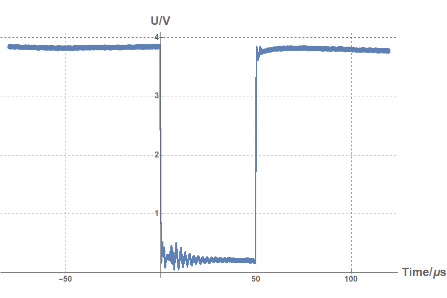

The trigger signal of CSRe injection is a TTL signal with a rapid falling edge from 4 V to 0 V. The width of it is 50 μs. Our goal is to catch the falling edge of the TTL signal and sending the triggered message to server, which can execute the IQ recorder to start acquiring. We chose an open-source microcontroller (Arduino Yun), which has a built-in Ethernet hub and supports Linux distribution, to realize the idea.
The circuit is to measure the voltage of the input TTL signal. Two identical resistors divide the applied voltage and a diode rectifies the current flow to protect the microcontroller.
As for the software part, we have tried two plans to catch the falling edge.
- Resetting the prescaler
The first idea was used in the beamtime of 2016. It resets the prescaler of the ADC to reduce the time for sampling the signal. However, the resetting has a high risk of shortening life of the ADC. - Using the analog comparator
The second has been used since the beamtime of 2017. It uses the the analog comparator to quickly pop a separate interrupt if the TTL signal is lower than the Bandgap reference (1.1 V). It does a nice job!
After getting the falling edge of the TTL signal (the rising edge of Analog Comparator Output), the library Process of the Arduino will run the shell-command netcat to send the triggered message to the server.
The trigger system with its box (applied to use in 2018):
remote-controllable button pusher for IQ recorder
From the result of thousands of off-line test, unstable original operating system (OS) of the IQ recorder is always the weak part of the whole system. Since the experiment platform is far from the control server, we design a special button pusher in case of the IQ recorder’s blue screen of death (BSOD).
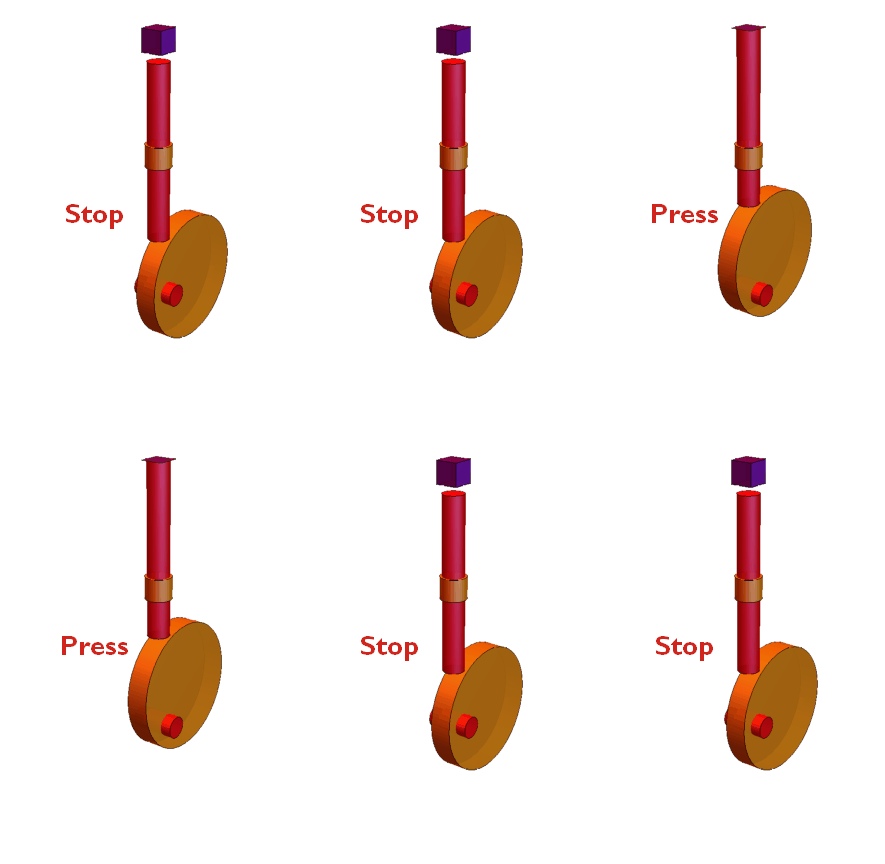
The mechanism of the button pusher is the cam, which transforms the rotational motion of eccentric wheel to the linear reciprocal motion of push rod.
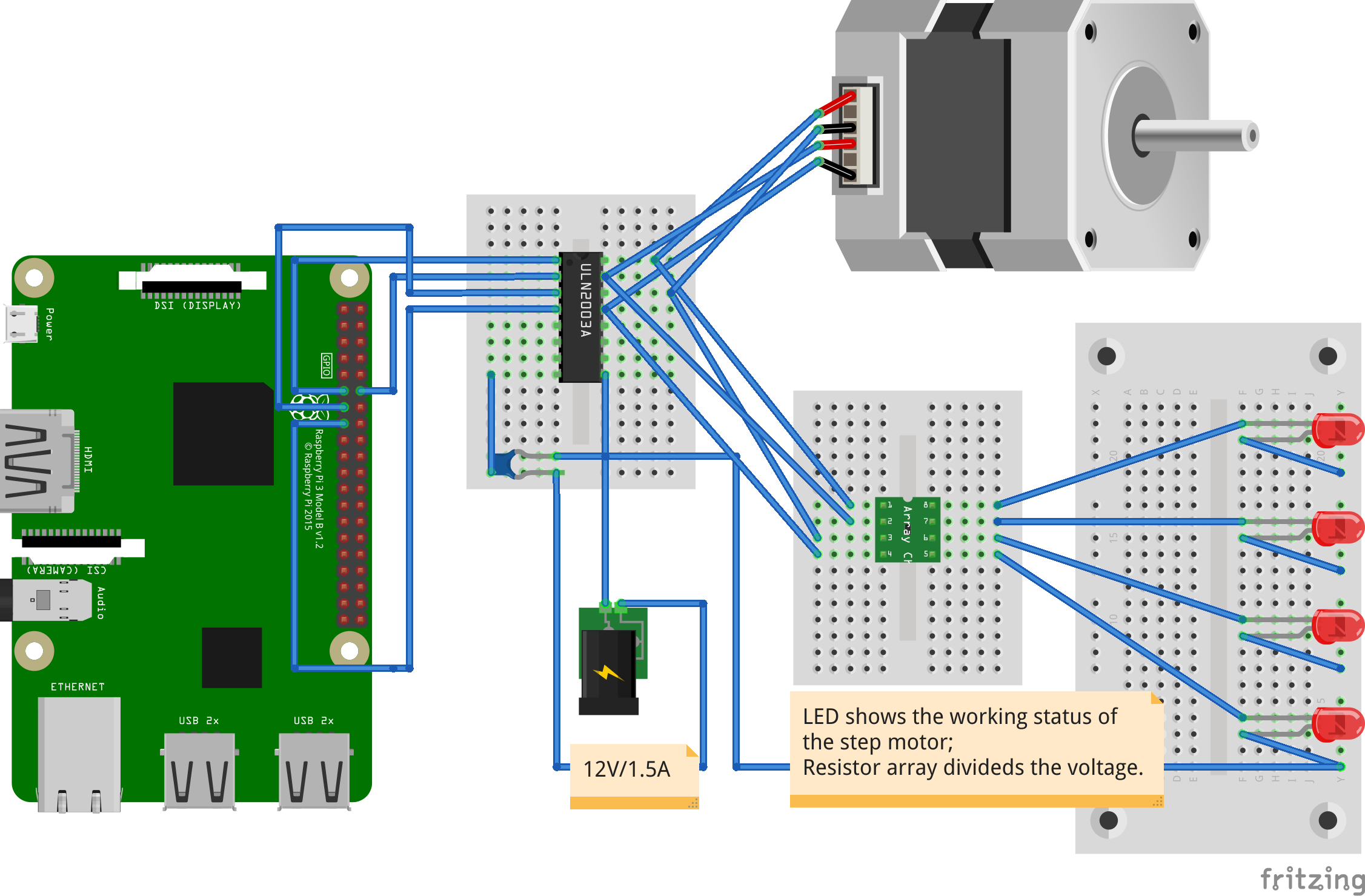
For the control hardware devices, we choose the raspberry pi, a ULN 2003 board for step driver control, a power supply (12V/1.5A) to provide enough electric power to the step motor.
Last is about the software of communication via network and the remote driver. A autorun program for the step motor driver control as well as the server to listen to the command from the remote main server is uploaded into the raspberry pi. A corrsponding client to send the command via the network is established in the remote main server. We send the commands from the main server to the raspberry pi, then the pusher will start to work as we wish.
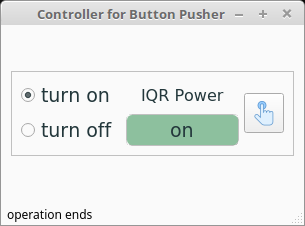
To get the user operation easiler and convenient, a GUI with two mode is built.
Normal mode (always shown, but disabled when the debug mode is selected)
- Turn on: use for booting the IQ recorder
- Turn off: use for shutdowning the IQ recorder (the time halt on button is longer than booting the devices)
Debug mode (only shown when pressing the key combination ctrl-h. pressing the combination again this mode is hidden again)
- step movement controller: use for calibrating the position of the push rod’s starting point
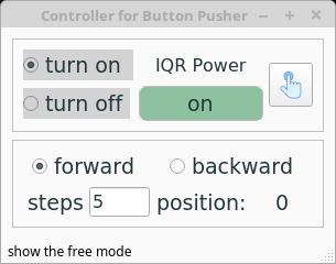
The detailed usage of the button pusher can be referenced from the repo’s README. The design details can be seen from the repo’s Wiki
The video of using the short press to turn off the of the IQ recorder
Software
The software has two version, command-line interface (CLI) and graphical user interface (GUI).
version 1. CLI
The first version was used in the beamtime of Dec. 2016 and Dec. 2017.
It is a simple and clear command-line interface. The users need to modify directly the source file to set acquisition parameters before launching the program. The progress of the processing devices is displayed in the interface. The key combination controls the system to pause, resume or terminate.
The interface:

The flow of the process:

version 2. GUI
The second version has been used from the beamtime of Jan. 2018 until now.
It is a user-friendly and effective graphical interface. After the physical connection and network driver deploy, the user can simply lanuch the program and control the system easily. All required parameters can be changed on the interface. Also several collecting modes and trigger modes are selectable.
The interface uses two threads. One is for the interface display and elements’ update. The other is for the processing devices’ work. The signal-slot mechanism helps the connection between two threads. By using the multithread, the probability of a hang or freeze will significantly reduce. Also the modular application facilitates troubleshooting and debuging.
The detailed usage of the GUI can be referenced from the repo’s README.
The interface:

The flow of the process:
